
Author: Henry Tol, PhD Candidate Aerospace Engineering, TU Delft
Article published in Leonardo Times Magazine, Edition of January 2017.
Turbulence and the transition to turbulence are recognized as unsolved problems in physics. Likewise, control theorists have hardly ever come across a problem this challenging. The goal of active flow control is to cross these interdisciplinary boundaries by considering the relevant flow physics when designing the control algorithms.
Motivation
The ability to control fluid flows to any desired state has great consequences for many applications. Imagine future aircraft where the traditional control surfaces (elevator, rudder, etc.) are replaced with flow control devices, which can accelerate the flow over the wings to generate lift and control moments. Currently, active flow control (AFC) is considered to be a viable route to further push the performance boundaries of aircraft. A recent demonstration of AFC technologies is the joint NASA/Boeing effort to enhance the aerodynamic efficiency of the vertical tail of the Boeing 757 ecoDemonstrator [1]. The vertical tail is equipped with 31 sweeping jet actuators to increase the effective sideforce generated by the rudder. They were able to maintain laminar flow and prevent flow separation on a highly deflected rudder. This increased the effective side-force and may enable a smaller vertical tail to provide the required control authority. This study indicated that the AFC-enhanced vertical tail could lead to an overall drag reduction of 1%, which in turn could save billions of dollars when applied worldwide. This is an example of so-called ‘open-loop’ control in which the actuator settings do not depend on real-time information of the flow. The actuator’s settings have been determined a-priori through extensive wind tunnel testing. This research is concerned with closed-loop flow control, in which real-time sensor information is used to devise controls that alter the flow in its desired state. Such systems are the most flexible, adaptive, and promising for efficient flow control. In this article, a new approach is outlined for closed-loop control of laminar-turbulent transition.
Classical transition scenario
Laminar boundary layer flows are characterized by parallel shear layers moving in a smooth, regular, and deterministic way. They have considerably less drag than their counterpart, turbulent flows, which are characterized by small-scale velocity components that appear chaotic in nature. Laminar flows are usually unstable and highly susceptible to external disturbances. These disturbances enter the boundary layer upstream through receptivity mechanisms such as free-stream turbulence or acoustic waves. In case of weak levels of disturbances, linear instabilities are triggered, dubbed Tollmien-Schlichting (TS) waves, in the form of nearly two-dimensional wave packets that propagate downstream and grow exponentially in space. As the amplitude of the wave packet grows above a critical level, three-dimensional and nonlinear interactions occur. In this stage, the disturbances grow rapidly, breaking down into smaller length scales, and transition until turbulence occurs. This is referred to as the classical route to turbulence [2]. The high sensitivity of laminar flows is also an opportunity for active control measures. By applying control through actuators/sensors acting only on a small localized part of the flow, a dramatic effect can be achieved by only minute amounts of control energy expense.
Control approach
The conceptual configuration for localised transition control is shown Figure 1. By suppressing the growth of small-amplitude perturbations early on, it may be possible to delay the entire process of laminar-turbulent transition. Wall-mounted sensors are used to detect the upcoming perturbations. Once detected, the perturbations are cancelled by localised forcing provided by the actuator. In this particular application, the sensor measures the shear stress at the wall. To manipulate the flow, zero-net-mass-flux blowing and suction are considered, which influences the wall-normal component of the velocity.
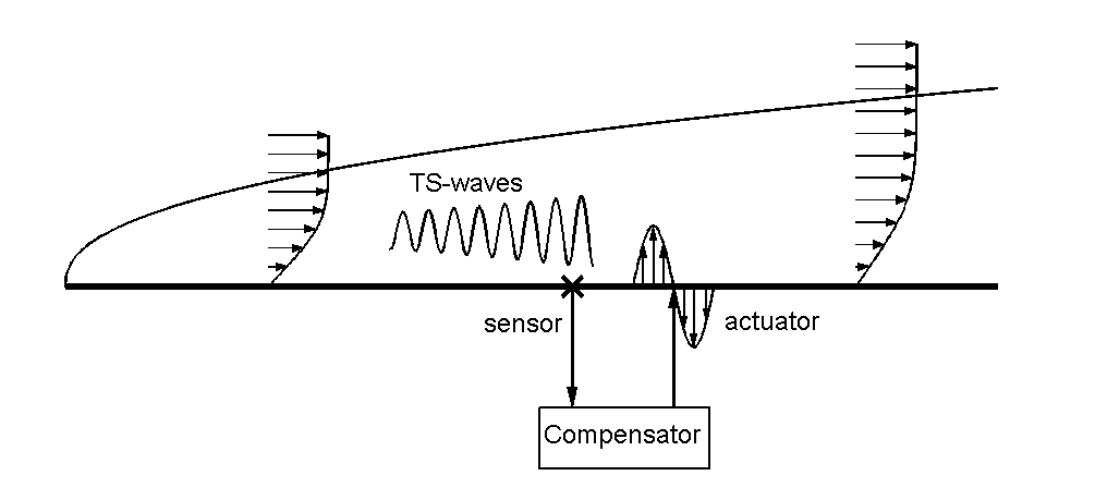
The sensor is placed upstream of the actuator to achieve the fastest disturbance attenuation. The dynamic compensator is at the core of the control system. It uses sensor information regarding the state of the flow along with a model of the flow to devise controls that alter the flow in its desired state. The largest challenge in such model-based control strategies is to find a proper mathematical model describing both the perturbation dynamics and the effect of the actuators/sensors on the flow. Fluid flows are complex and thus challenging to model accurately. The complete modeling of the flow exceeds the available computer power by many orders, particularly for online applicability. The Navier-Stokes equations, in perturbation form, describe the full perturbation dynamics, and once-discretised, results in very high dimensional systems. Actually, when viewed as a dynamical system, it has an infinite dimension, meaning it has infinite number of perturbation modes and eigenvalues. Fortunately, nature is forgiving and the perturbation modes, or TS-waves, are only unstable in a limited frequency band in both space and time. This is a typical property of so-called parabolic PDE systems, and the dominant dynamics can accurately be captured using ow order models [3]. The idea is to extract the key features of the flow that contribute to transition and represent them in a simpler reduced order model, develop ways of controlling the model, and apply the results to the original fluid flow. Multivariate splines [4] are used to construct the control models [3]. It is one of the most flexible and powerful spatial basis function and function approximator. It can be considered to be a generalization of the finite element to arbitrary degrees and any order of inter-element continuity. Figure 2 shows such a two dimensional spline element of degree four. The ‘coefficient net’ shows the control points of the element and represents the discrete states. Using a spline expansion of the flow field, the Navier-Stokes equations can be spatially discretized. This results in a finite dimensional spline state space model (set of ODEs) of the flow, which can be used to design any suitable compensator using classical control theory approaches. Splines are very user-friendly for creating the control models. They are defined on triangular meshes, can approximate any domain, and use local refinements in the control region, e.g. the region with the sensors and actuators, to extract the key features of the system. Secondly, they are general in terms of smoothness and degree, allowing for a high ‘spectral like’ resolving power. In fact, the degree and order of continuity of splines are simply input variables for creating the state space models. This method is used in conjunction with balanced truncation for state space systems to synthesize low order controllers that can be implemented for real-time application of flow control.

Results
To demonstrate the effectiveness of the proposed control approach, a flow over a flat plate is considered including an adverse pressure gradient. The flat plate is scaled in the terms of the Reynolds number with the outer streamwise velocity, the kinematic viscosity and the streamwise location at the plate. External disturbances are introduced in the flow through stochastic forcing, or a ‘vibrating ribbon’, located upstream of the control domain. This disturbance excites a broad frequency spectrum, introducing TS wave packets that propagate downstream. To cancel the wave packets, a low order controller is designed which employs a point wall shear measurement for feedback and wall-normal blowing and suction to manipulate the flow. The controller is designed without any a-priori knowledge about this specific disturbance source. It only has fifty degrees of freedom while the simulations are conducted with more than 50,000 states. Figure 3 visualizes the spatial evolution of the perturbation field, including the location of the actuator, sensor, and the disturbance source.
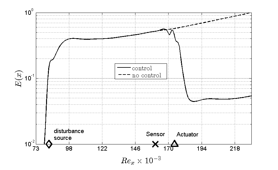
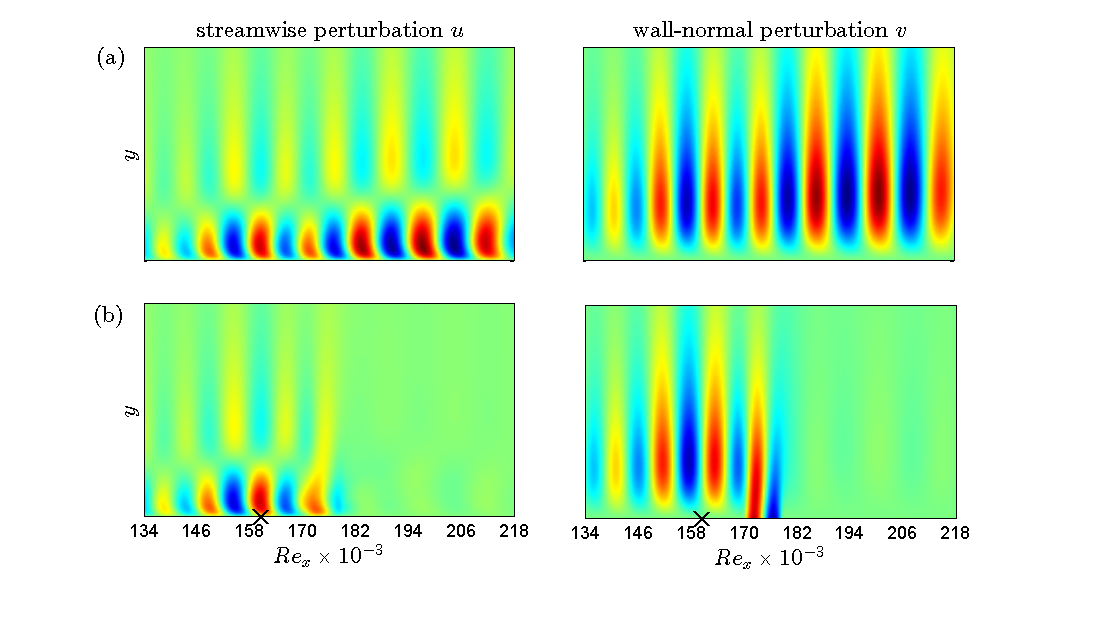
It shows the normalized perturbation energy along the plate integrated in both the wall-normal direction and in time. In addition, a snapshot of the flow at a particular instant in time is shown in Figure 4. Both the uncontrolled and controlled flow are shown. It can be observed that the controller significantly supresses the perturbations. The perturbations grow only until it reaches the actuator position at which point it begins to decay due to the blowing and suction actions. The effect of the actuator at the wall can clearly be observed in Figure 4. By applying actuation on only a small part of the flow, the perturbations are supressed in the entire upstream region, thereby delaying the onset of laminar-turbulent transition.
Next step: wind-tunnel experiments
It has been shown that model-based feedback control is effective in maintaining a laminar flow and in delaying transition to turbulent flow. The results presented in this article are still at a proof-of-concept level. Experimental implementation will soon begin, as well as validation of this method in a wind tunnel. Plasma actuators [5] will be used to manipulate the flow. Using advanced system identification techniques, plasma body force models will be identified and integrated in the control methodology. Plasma actuators have a very fast frequency response and can instrument fluid flows on short length and time scales. Combined with closed-loop control it will hold great promise for future industrial applications of flow control.
If you have further ideas or want to contribute to this research as a graduate student, contact the author for further information by email [email protected]