
Engineering relies heavily on mathematical models of real systems. However, physical processes are often highly complex and not entirely understood, so the modeling of the first principles can be challenging, sometimes even impossible. System identification allows for any system, however complex or obscure, to be modeled solely on the basis of measurements.
System identification is the science of extracting a model from a set of observations or measurements. By looking at how a system behaves in specific situations, we can determine whether there are patterns in the behaviour and what factors influence it. The underlying idea is to formulate a basic model structure containing a number of unknown parameters, and then estimate these parameters such that the difference between measurements and model-predicted outputs is in some way minimized. The model structure can be based on assumptions, prior knowledge of the system or experience with similar systems. It can be inferred from observation, or even arbitrary, but also adjusted and refined within the identification process.
The final result is a mathematical model of a system, essential in every field of engineering. As in daily life, engineering tries to explain and predict behaviors so that we may know how one event leads to another, allowing us to influence and manipulate the world around us to our advantage. We may not know whether our interpretations are correct, but we can establish whether they provide accurate descriptions. Broadly speaking, even fundamental physical laws can be seen as the result of a system identification approach. Newton’s gravitation law, for instance, was inferred from the observation of free-falling objects. It does not explain what gravitation is, but it yields an extremely useful model that works in practice.
System identification is a powerful tool that can be applied to model practically anything, ranging from aircraft aerodynamics to the weather and climate. A model can be computed even when little is known or understood about the real system, as long as relevant measurements are obtained. This not only allows us to approximate highly complex systems that are difficult or impossible to model from first principles, but also is advantageous even for well-known systems. The use of experimental data can yield detailed and realistic models, while the possibility of incorporating prior knowledge in the modeling process ensures accuracy.
The resulting models are typically used to run simulations, to design and run controllers, or simply to explain or analyze the system in question. By modeling a system we can often learn something about it, hence system identification also provides a means of analyzing and better understanding new, highly complex, or not fully understood systems.
In the aerospace field specifically there are many exciting applications of system identification. Some of the ones currently being researched at TU Delft are introduced in the next sections. These include sensor calibration, aerodynamic modeling of flapping-wing aircraft and satellites, development of new, flow-based control methods and safe operation of damaged aircraft.
Sensor calibration
(Dyah Jatiningrum)
The starting point for every system identification effort is a set of observations. In aerospace applications, these are generally sensor measurements. For a complex structure such as an aircraft, sensors are essential elements in the flight control and navigation systems. Correct data has a significant role in ensuring that everything runs smoothly, safely, and accuracy is maintained. Among others, inertial sensors such as accelerometers and rate gyroscopes are the core provider of aircraft motion and orientation feedback. This is why researchers strive to improve their performance. To have an accurate measurement of response characteristics, sensors must meet stringent specifications, which can be evaluated with high-standard calibration techniques.
In the era of modern, highly accurate and robust sensors, one might wonder why a calibration is even necessary. The truth is that sensors are still physical measuring devices. This means that their construction is imperfect and that their operation is influenced by environmental factors. In practice, these effects lead to errors in the measurements that, if left uncorrected, would result in inaccurate data and potential failures of the system.
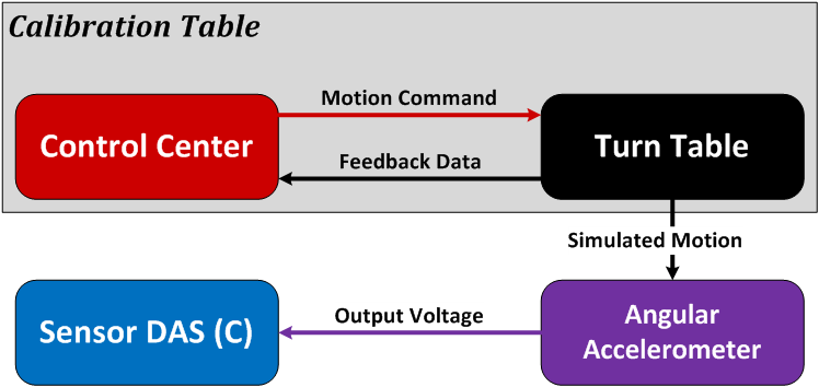
Current research focuses on angular accelerometers- novel inertial sensors that may play a substantial role in future fault-tolerant flight control systems. The biggest challenge in calibrating angular accelerometers is the lack of equipment and of available standards. Nevertheless, a distinctive calibration procedure utilizing a position-based turntable could help to meet these challenges. The envisaged setup is shown in Figures 1-1 and 1-2.
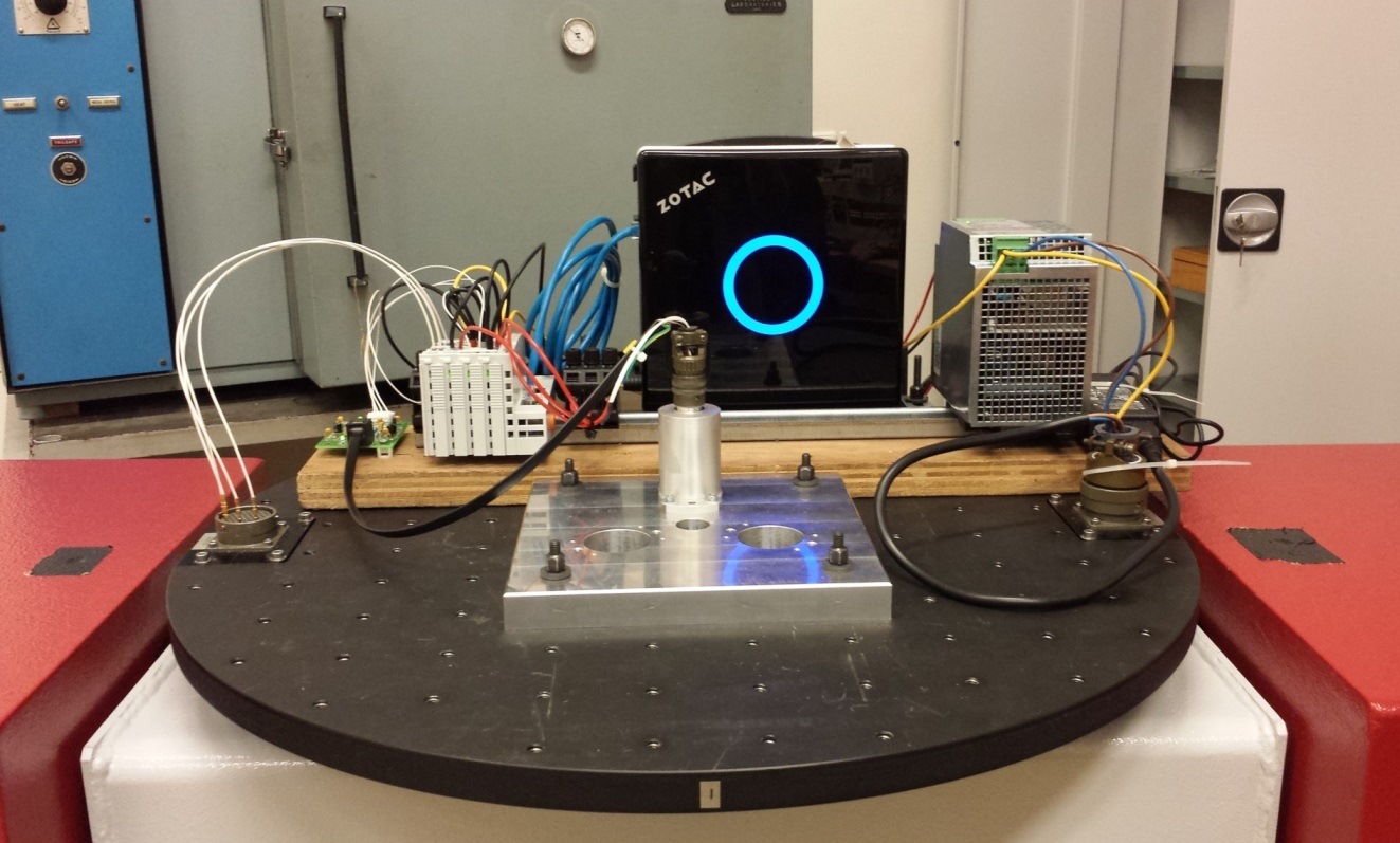
The calibration will require a dynamic performance evaluation, in addition to the static performance. This becomes an issue since the available equipment has a significantly less accurate dynamic capability. Through a careful investigation, a test envelope is established as a guideline for the cutting-edge sensor’s measurements. It determines the limits for a safe equipment operation, and additionally guarantees a suitable input excitation for the angular accelerometer.
Furthermore, a reliable sensor model is essential in the early stages of sensor-based, fault-tolerant flight control system design. This study develops a suitable system identification technique to obtain the angular accelerometer characteristics represented in the model. In the case where the individual component values are not known, the frequency response of the system from input to output can be obtained experimentally and used to determine the transfer function.
In short, the critical assessment of the angular accelerometer is not as straightforward as that of the regular inertial sensor. However, the difficulties involved can be solved in the current research using adjusted calibration strategies for the widely available calibration table. Additionally, the angular accelerometer limitations and performance characteristics can be recognized using a system identification principle.
Modelling flapping-wing micro aerial vehicles: the DelFly
(Sophie Armanini)
When systems are very complex or not well known, a data-driven approach can provide valuable insight. This is, for instance, the case for flapping-wing micro aerial vehicles (FWMAVs): a novel, bio-inspired type of unmanned flight vehicle. From the study of insects and birds, flapping-wing mechanisms are known to be extremely effective for small-scale flyers operating at low velocities, endowing these with high maneuverability and agility, hover capability, power efficiency and an extensive flight envelope. These advantageous properties render FWMAVs particularly suited for flight in cluttered, inaccessible or hazardous environments. Moreover, with advances in miniaturization it is possible to install increasingly accurate miniature cameras and sensors on such vehicles, allowing for a wide range of applications in the future. FWMAVs could perform search operations, be used for ISR (Intelligence, Surveillance and Reconnaissance), or inspect damaged buildings or machines.
However, at present FWMAVs are confined to university labs. Flapping-wing aerodynamics are predominantly unsteady, involving mechanisms such as leading-edge vortices and clap-and-fling, which are difficult both to understand and to model. The flapping motion also results in complex time-varying kinematics and dynamics. Relying on highly complex and not fully understood mechanisms, FWMAVs are challenging to develop and their potential cannot yet be fully realized.
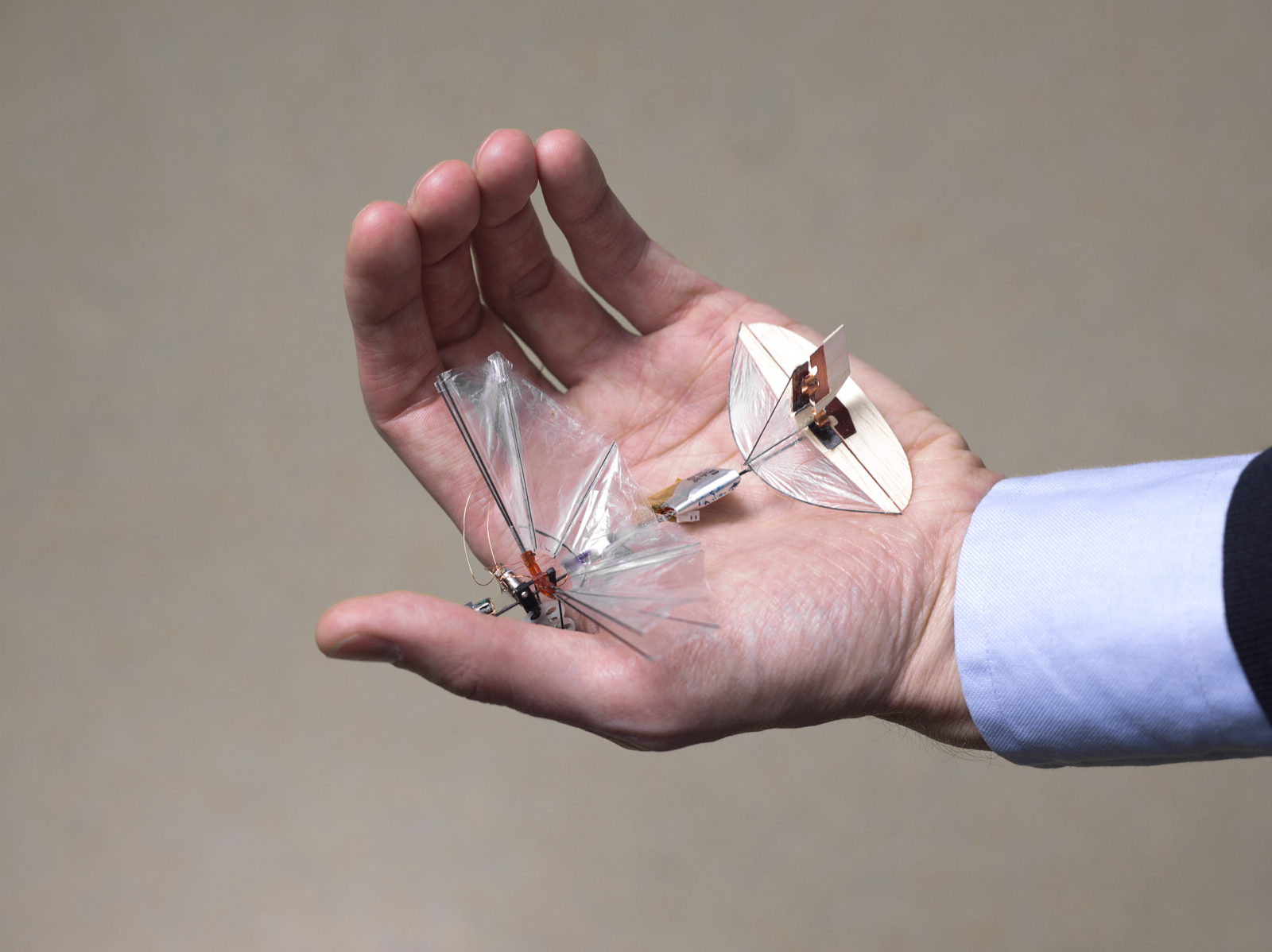
At TU Delft, flapping-wing research is centered on the DelFly, the university’s in-house FWMAV. The smallest configuration so far, Deafly Micro (Figure 2-1), has a wingspan of 10cm and weighs 3g, including an on-board camera. A significant part of this research involves investigating the dynamics and aerodynamics of FWMAVs, and developing models for simulation and control purposes. For instance, accurate aerodynamic models are required for advanced model-based controllers, which would enhance FWMAV performance and autonomy.
Control and simulation applications require models that are accurate but also useful in practice. Model identification comes in handy here, as opposed to computational fluid dynamics or first principles, which often yield over-simplified or exceedingly complex and computationally intensive models. Identification additionally handles incomplete knowledge of the platform effectively, and capitalizes on the unique FWMAV free-flight data that the optical tracking system of the TU Delft flight arena (Cyberzoo) allows us to obtain.
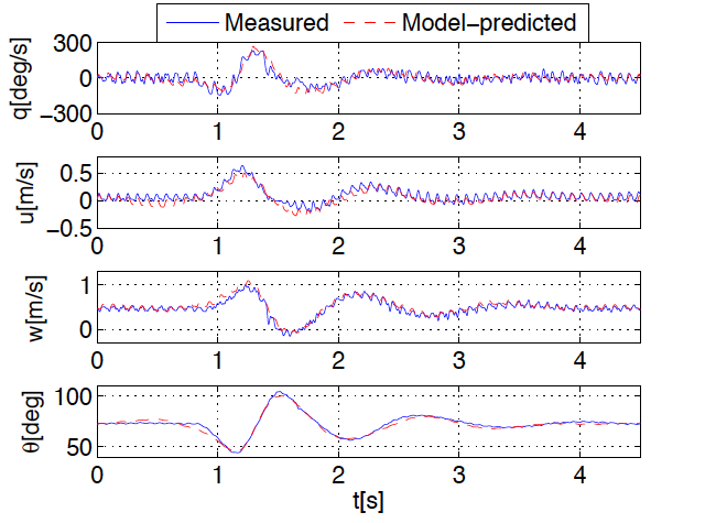
The modeling process yields accurate, low-order models, such as that shown in Figure 2-2, but can also be used to generally enhance current understanding and knowledge of the DelFly and flapping-wing mechanisms, and to devise and experiment with new designs. Thus, this research will provide both a better understanding of flapping-wing flight, and more effective simulation and control possibilities, supporting the development of more effective platforms that in the future may be used beyond the bounds of research.
Satellite aerodynamic model identification
(Tim Visser)
A similar data-driven approach can also be used to model completely different systems. A second example is the aerodynamic torque acting on a satellite. Satellites are often thought to move through empty space, relieved from the aerodynamic friction, which drives aircraft performance and design. However, there is a limit to the validity of this assumption. Rather than a bounded balloon of air, the atmosphere of the earth is an ever-changing gas layer of exponentially decreasing density, with a gradual transition to vacuum. Although the air density at LEO altitudes (Low Earth Orbit, 200 to 500km) is generally a factor of 100 billion lower than at the earth’s surface, aerodynamic drag is often the dominant disturbing force for satellites at these altitudes. Thrusters are required to keep them in the desired orbit- the effects of the drag being so great that an altitude of 200km, a satellite without active drag cancellation will re-enter the lower parts of the atmosphere within weeks.
Due to the lack of direct density measurements in the thermosphere however, the drag force is hard to predict. In fact, for all modern models of the higher atmosphere, the orbital decay of satellites in LEO is used to arrive at an estimate of the density. However, this value is derived based on an assumed drag coefficient. The users of these models again estimate their drag coefficient based on experience from previous missions, and combine this with the density from the models to predict the drag. In other words, the product of density and drag coefficient is well known, but the distribution of the value over the two variables is purely based on an estimate of the coefficient.
Recent research at our faculty into the extremely accurate accelerometer data gathered by the Gravity field and Ocean Circulation Explorer (GOCE), shown in Figure 3-1, has led to new insights into the aerodynamic forces on a satellite at 250km altitude.

By deducing all other known forces from the linear accelerations, the aerodynamic force in all three directions could be derived. Using a physical particle-surface interaction model to find the aerodynamic coefficients, the density could be calculated from these measurements; yet these densities turned out to be significantly different from the model-predicted values.
Current research is aimed at adding the aerodynamic moments to the model of GOCE. This will result in the first high-fidelity aerodynamic model of a satellite. Using the latest developments in the field of multivariate splines, the remaining unknown parameters, such as the density, may subsequently be estimated. Finally, we may validate existing density models using actual in-orbit measurements.
Flow modeling for control
(Henry Tol)
Models are required not only purely to investigate a system’s behavior, but often also for control methods, particularly ones relying on complex phenomena such as airflow. The ability to control flows to fit any desired state has significant consequences in aerospace applications. Imagine future aircraft where the traditional control surfaces are replaced with flow control devices, which can accelerate the flow over the wings to generate lift and control moments. Currently flow control is considered a viable route to further push the performance boundaries of transport aircraft for drag reduction, noise suppression and lift enhancement. For example, numerical studies have shown that an average drag reduction of more than 20% can be achieved by closed-loop active flow control (AFC). In closed-loop AFC one utilizes sensor information regarding the state of the flow along with a model of the flow to devise controls that alter the flow in its desired state.
Fluid flows are complex and thus challenging to model fully and accurately. The complete modeling of flows exceed the available computer power by many orders, particularly for online applicability. This observation is at the heart of the reduced-order model approach. The idea is to extract the key features of the complex system and represent them in a simpler reduced-order model, develop ways of controlling the model, and apply the results to the original fluid flow.
The multivariate spline is a very powerful tool to create reduced-order models for flow control. Using a spline expansion of the flow field, the Navier-Stokes equations can be spatially discretized. This results in a B-spline state space model (set of open dynamics engines, ODEs) of the flow that can be used to design any suitable controller and observer. B-splines are very user-friendly. First, they are defined on triangular meshes allowing to approximate any domain and to use local refinements in the control region, i.e. the region with the sensors and actuators, to extract the key features of the system. Secondly, they are general in terms of smoothness and degree, allowing for high ‘spectral-like’ resolving power. In fact, the degree and order of continuity of splines are simply input variables for creating the state-space models. As an example, Figure 4-1 shows the steady-state solution for the lid-driven cavity flow at a Reynolds number of 1000 using splines of degree ten and second-order continuity. Even on a coarse triangulation (36 triangles) an accurate solution is obtained which captures the physics of the flow.
Online Physical Model Identification for Safe Flight Envelope Prediction of Damaged Aircraft
(Ye Zhang)
A major advantage of novel system identification techniques is that they can be applied in-flight, for example in the case of damage to the aircraft. Past aircraft accidents, such as damage to the aircraft itself, often leads to aerodynamic instability, loss-of-control and can be fatal. To aid the pilot and automation system to be fully aware of the current situation and increase the possibility of maintaining controlled flight from an otherwise completely non-recoverable situation, a safe flight envelope is needed. The flight envelope is defined as a limitation of aircraft states bounded by aircraft structural and performance characteristics. However, if the aircraft is damaged, the current flight envelope is no longer valid and a new safe flight envelope will soon be needed, indicating the reachable flight states given limited control authorities and a changed aircraft model.
The core to obtaining new safe flight envelopes under off-nominal conditions is the online model identification of the aircraft. When the pilot’s command is given and control inputs are fed in, the measurements from sensors will be filtered to estimate the current states and instrumentation biases through kinematic and observation models of the aircraft. At the same time, the system will also need to examine the health of actuators by comparing the actual deflections measured by sensors and the expected values from prior actuator models with predefined or adaptive thresholds. In the following steps, the estimated states and mass properties will be used to identify the aerodynamic model of the aircraft using polynomial models or more advanced spline models. Under off-nominal conditions, measurements from sensors can only be obtained in the vicinity of current states, therefore only a local aerodynamic model can be calculated. Nevertheless, we can get a rough estimation of the current debilitated physical condition of the aircraft even with this identified local model.
The identified physical model of the damaged aircraft includes the type, position and severity of the damage. Assuming only one damage case occurs at one time, and the changes of aerodynamic forces, moments and coefficients caused by structural damage have been isolated and calculated, then the identification of a physical model can be realized by monitoring and comparing the aerodynamic components that each damage case has the most dominant and unique effects on. The identified physical model will not only improve the self-awareness of the pilot, but most importantly, it can also link the online identification steps to the offline generated database of safe flight envelopes that would greatly enhance the safety of the aircraft.
Conclusion
System identification-based research is extremely multi-faceted. The selection of examples discussed here only covers a small part of the aerospace domain, and the method is by no means restricted to this or any other particular field. Furthermore, the identified models have many different applications. They can improve our understanding of a system, but also be used to control or simulate the modeled system, or even to improve its design or operation. The possibility of using system identification both in many different contexts and for many different purposes, allows for a huge variety of applications.
Students interested in thesis projects or PhD research in this field are invited to contact the authors for further information.
[author] [author_info]
Dyah Jatiningrum, PhD Candidate, Aerospace Engineering, Control & Simulation and Agency for the Assessment and Application of Technology, Indonesia
Sophie Armanini, PhD Candidate, Aerospace Engineering, Control & Simulation
Tim Visser, PhD Candidate, Aerospace Engineering, Astrodynamics and Space Missions and Control & Simulation
Henry Tol, PhD Candidate, Aerospace Engineering, Control & Simulation and Aerodynamics
Ye Zhang, PhD Candidate, Aerospace Engineering, Control & Simulation
Coen de Visser, Assistant Professor, Aerospace Engineering, Control & Simulation
[/author_info] [/author]