
With the depletion of fossil fuels, increasing emissions, and the inevitability of global warming, the interest in renewable energy grows. Conventional solutions, like horizontal axis wind turbines, are reaching the limits of their capabilities. Therefore, there is renewed interest in other models, such as the Vertical Axis Wind Turbine (VAWT).
While there are multiple variations on the VAWT, the most viable one is the Darrieus turbine, patented in 1932 (Darrieus, 1931). This turbine operates on the principle of aerodynamic forces acting on vertically placed blades, spinning around an offset center. When enough torque is generated, power is produced. The advantages of this configuration are that it is easily scalable, will not suffer from gravitational loads and has a low center of gravity, as heavy parts like the generator are placed near the surface (Eriksson, 2008). Especially the latter characteristic make it a good contender to its horizontal axis counterpart, as a VAWT can easily be placed on floaters and anchored in the deep sea (Akimoto, 2011). For the HAWT (Horizontal Axis Wind Turbine) this is far more problematic and costly, as placing an offshore HAWT can be even more expensive than the turbine itself (Moné, 2014).
The VAWT , however, has some downsides as well. The blades pass through their own wake, it has a difficulty self-starting, and no stall mechanism so far has been invented that is safe enough. The aerodynamics associated with them are so complex that it currently remains difficult to understand or model these phenomena. However, it is thought that some of these problems can be mitigated through custom airfoil design (Migliore, 1980). Accurate modelling of VAWT aerodynamics will result in improved airfoils and has the possibility to enhance the turbine output. Therefore, this makes for an interesting and cutting-edge research field.

A specific aerodynamic phenomenon was highlighted in this research, namely flow curvature. This phenomenon arises as a VAWT airfoil not only has a translational motion, but also a rotational one. As a result, the angle of attack varies over the chord. Namely, the rotational velocity at each point on the chord is normal to its local radius. This variation of angle of attack has large repercussions on the performance of the airfoil, and therefore also the blades. In essence, an airfoil orbiting the VAWT center will act as having added camber and added angle of incidence to the flow (Zervos, 1988). Specifically, the added rotational motion alters the surface velocity of the airfoil. The pressure distribution, in turn, is then changed and eventually this alters the aerodynamic forces and their azimuthal distribution. In the end, a change in power output and efficiency of the turbine is experienced. Previous research has shown that this will almost always result in negative outcomes.
Now if these flow curvature effects can be estimated and accounted for, advantages can be made in the turbine design and its performance. This was the objective of this research. Below, a concise summary of its outcomes is presented. It shows how researchers in the past have dealt with flow curvature, and presents a novel method to do so. It will be shown that this new simulation model has merit for future VAWT design.
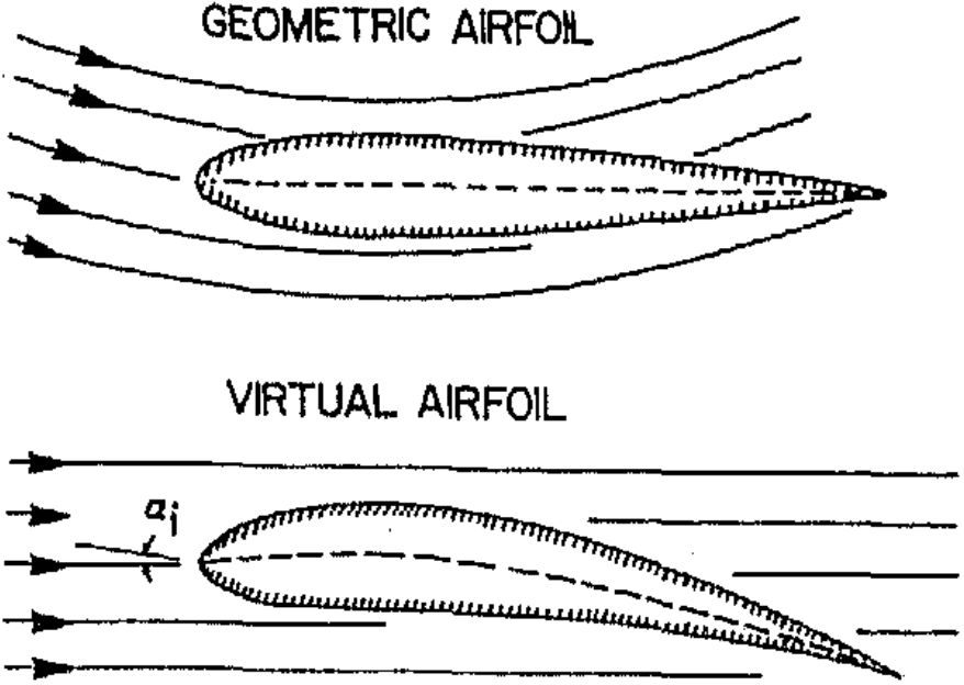
The impacts of flow curvature have been investigated as early as 1975, and are thoroughly described by Migliore, 1980. Similar to several other authors, their method to implement flow curvature was by modifying the actual airfoil of the turbine to a virtual one, incorporating an approximation to the flow curvature. In Figure 1, one can see such an approximation, where in order to “bend the curved streamlines of the VAWT airfoil straight, the virtual airfoil is bent as well”. The latter airfoil will obtain a camber and an incidence angle according to the original situation, but now operates in straight flow. This means that it can be investigated using conventional methods.
Several authors present methods to perform such a virtual airfoil transformation, while only six of these describe their work detailed enough to be reproduced. An important parameter in all these methods is the chord-to-radius ratio of the turbine. One can imagine that if this ratio increases, the variation of angle of attack over the chord will increase, resulting in enhanced flow curvature effects. Their transformations have been applied to investigate any performance differences. A visual inspection and a calculation of their pressure distribution showed that for common chord-to-radius ratios below 0.2 (Kirke, 1998), no distinguishable differences or advantages of any method could be found.
The virtual airfoil transformation solutions have been computed by the use of the U2DIVA panel code (Simão Ferreira, 2009). This inviscid potential flow solver uses singularity solutions placed on the airfoil surface to compute the airfoil characteristics, such as pressure distribution and aerodynamic forces. With a small modification, the option to also include the additional surface velocities of a rotating VAWT airfoil was added. This alteration has been verified to produce the correct result, and could therefore be used to compare the transformed airfoils to. Finally, it has been observed that all the methods perform equally well when regular design parameters of current turbines are applied.
Please note that these outcomes only concern inviscid, so “theoretical” results. For real-life situations, viscous calculations are necessary. A proven method of designing airfoils for such cases is the XFOIL panel code. This software, developed in the eighties at MIT (Drela, 1989), allows the user to easily apply an inviscid potential flow solver coupled with viscous boundary layer calculations. In essence, it can make calculations for airfoils in real-life situations.
XFOIL’s inviscid solver revolves around the principle of the stream-function. This is a potential flow solution for a singularity or a distribution of these. As the original source code assumes straight flow, some modifications were necessary to include a rotating VAWT airfoil. This airfoil can be simulated by an airfoil continuously rotating about an arbitrary axis within the airfoil itself. Namely, the motion of the original VAWT airfoil only differs from such a simulated airfoil by its translational motion due to the VAWT arm. By removing this arm, both airfoils rotate about the mounting location of the airfoil. Obviously, the kinematic equations will change, and a derivation of this similarity can be made to be a very significant result. This says that varying the normalized rotational velocity of the airfoil can simulate the chord-to-radius ratio, on which flow curvature effects depend. This provides for an excellent opportunity to implement in XFOIL.
The stream-function formulation of the potential flow solver has been modified to include new boundary conditions of an airfoil with arbitrary rotational velocity and center of rotation. As now, the reference frame is rotating, a change in the computation of pressure coefficient has to be made. The method of computing the surface velocities of the airfoil is also modified, as the original code was incompatible with the new modifications. A result is shown in Figure 2, where the pressure distribution of a NACA0015 airfoil computed by XFOIL is compared to the U2DIVA benchmark, for a chord-to-radius ratio of 0.2 and a mounting location at half the chord. The inviscid solution showed that no cumulative differences between the computed pressure distribution and the benchmark larger than 10% have been found (i.e. be- tween the lift coefficients). It is assumed that with the modified potential flow solver, the viscous calculations can be left untouched and should perform as before. As there are no viscous benchmark solutions for rotating airfoils, this cannot be verified.

A final investigation into airfoil optimization and turbine performance was performed with the newly modified version of XFOIL. Using optimized software based on a genetic algorithm, numerous different airfoils were generated and analyzed for their aerodynamic and structural properties. The optimiser scores each airfoil on two objectives, one to optimize the power output of the turbine and the other to maximize the area moment of inertia of the airfoil so as to obtain a blade which is as stiff as possible (Simão Ferreira, 2015). The result is a whole range of optimised airfoils, varying from very aerodynamic and not so stiff, to structurally optimal and aerodynamically infeasible. Only the former are used in further investigations.
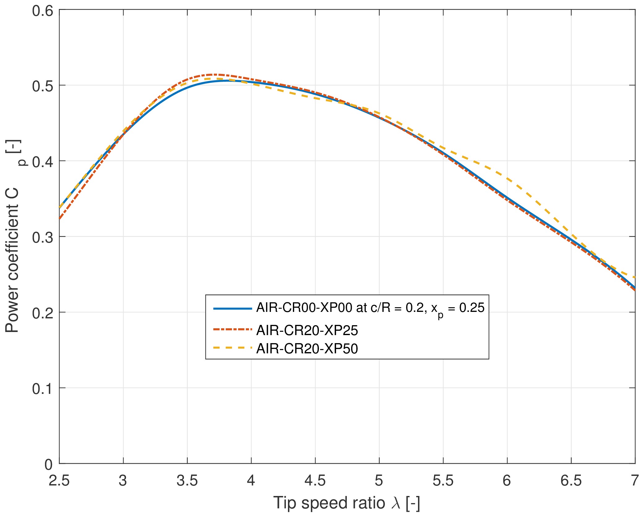
Under the same circumstances, airfoils optimised for straight flow were compared to ones optimized while rotating. In this manner, one would be able to see if a power improvement could be obtained. Using software, the turbine power output over a range of operating conditions was simulated. Figure 3 shows the power coefficient calculated for three airfoils- the first is an airfoil optimised for straight flow, but simulated while rotating around its quarter chord. The latter two are airfoils optimized for rotating flows, one turning about the quarter chord and the other about the half chord location. As can be seen, up to a tip speed ratio of five, which is the region typical for a VAWT, at least one the airfoils optimized with the inclusion of flow curvature performs better. Even though the difference is small, the potential for power enhancement can be recognized.
Although the above simulations lack some verification and surely need to be extended and improved, there are clear signs that the presented method can lead to improved tailored airfoil designs for vertical axis wind turbines. Including such a virtual modification of the rotating airfoil is currently not applied in the design process, but shows that increased turbine power output and efficiency can be obtained. This will not only aid in the proliferation of VAWTs, but of wind energy in general, hopefully solving our global energy crisis in the future.
– Ir. Sander van der Horst
References:
[1] J. Moccia, “European Wind Energy Association: Wind energy scenarios for 2020”, 2014.
[2] G.J.M. Darrieus, Turbine Having Its Rotating Shaft Transverse to the Flow of the Current”, 1931.
[3] S. Eriksson, H. Bernhoff, and M. Leijon, “Evaluation of different turbine concepts for wind power”, Renewable and Sustainable Energy Reviews, vol. 12, no. 5, pp. 1419– 1434, 2008.
[4] H. Akimoto, K. Tanaka, and K. Uzawa, “Floating axis wind turbines for offshore power generation – a conceptual study”, Environmental Research Letters, vol. 044017, no. 6, p. 6, 2011.
[5] C. Moné, T. Stehly, B. Maples, and E. Settle, “2014 Cost of Wind Energy Review”, National Renewable Energy Laboratory, Tech. rep., 2014.
[6] P. G. Migliore, W. P. Wolfe, and J. B. Fa- nucci, “Flow Curvature Effects on Darrieus Turbine Blade Aerodynamics”, Journal of Energy, vol. 4, no. 2, pp. 49–55, 1980.
[7] A. Zervos, “Aerodynamic Evaluation of Blade Profiles for Vertical Axis Wind Turbines”, in European Community Wind Energy Conference, Herning, Denmark, 1988, pp. 611–616.
[8] B. K. Kirke, “Evaluation of Self-Starting Vertical Axis Wind Turbines for Stand-Alone Applications”, Ph.D. dissertation, Griffith University Gold Coast Campus, 1998.
[9] C. J. Simão Ferreira, “The near wake of the VAWT 2D and 3D views of the VAWT aerodynamics”, Ph.D. dissertation, Delft University of Technology, 2009.
[10] M. Drela, “XFOIL: An Analysis and Design System for Low Reynolds Number Airfoils”, Lecture Notes in Engineering, vol. 54, pp. 1–12, 1989.
[11] C. Simão Ferreira and B. Geurts, “Aerofoil optimization for vertical-axis wind turbines,” Wind Energy, vol. 18, pp. 1371–1385, 2015.